
Four Steps for Testing Your SeaDoo’s Fuel Sending Unit
Paul Martin of Arnold, Missouri got a wicked deal when he bought his used SeaDoo. But when he took it out for the first time on the lake, the fuel sensor didn’t appear to be working. The previous owner claimed the fuel sensor worked when he had it and so Paul was faced with getting the fuel sensor replaced, repaired or fixing it himself. Fortunately, Paul likes to take things apart but before he did he came to Jet Ski Plus for some advice. Here’s what we shared with Paul about testing his SeaDoo’s fuel sending unit.
Inside your SeaDoo’s fuel tank is a plastic tube known as the fuel pickup, and within this tube is an integrated fuel sending unit. The sending unit is made up of a long narrow circuit board with 9-12 Reed switches and several resistors. These Reed switches and resistors are wired so that the total r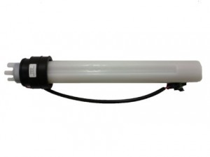 esistance across the circuit board increases as each Reed switch closes from the bottom of the tank to the top. Regardless of the model and year of your SeaDoo, the resistance ranges from 90 to 0 Ohms, with 90 Ohms representing an empty tank and 0 Ohms representing a full tank. These Reed switches are activated by a magnet attached to a float that rides up and down internal rails with the fuel level.
While the design is simple, the weak link in the system is a one-time fuse on the fuel sending unit’s circuit board. Once the fuse blows, the sending unit is rendered non-functional since the fuse can’t be replaced. Here are the steps we recommend for testing the fuel sending unit for 2-stroke carbureted SeaDoos. Unfortunately, these steps won’t work on fuel injected or 4-TEC SeaDoos.
This quick and easy test will help you diagnose most common problems with the fuel sending unit and doesn’t require you to remove the fuel baffle from the tank. All you need is an Ohmmeter and some time.
- First, you’ll want to locate the fuel sending unit and sending wires. Potted into the side of the fuel sending unit, the wires are pink and pink/black. Follow these wires until you come to the inline 2-wire connector and then disconnect the connector.
- With the connector disconnected, you’re ready to perform a resistance test on the fuel sending unit. This is accomplished by connecting the Ohmmeter to the pink and pink/black wire terminals running to the fuel sending unit.
- With the Ohmmeter connected, you’ll want to record the resistance and approximate level of the fuel in the tank.
- Next, compare your readings with the following that are typical on a good sending unit:
- 0-5 Ohms (Full Tank)
- 45+/- Ohms (Half Full Tank)
- 85-95 Ohms (Empty Tank)
If your Ohmmeter shows an open circuit or infinite resistance, the internal fuse is blown and the sending unit will need to be replaced.
If your ohmmeter reads 85-95 Ohms and the tank obviously has gas, either the float has lost its buoyancy or the magnet has come loose from the float. If either is the case, your fuel gauge would always show an empty tank of gas. In this case, you’ll need to install a new float into the sending unit.
If your fuel gauge seems to be stuck or show the same reading, the float could be wedged inside the plastic tube. Though rare, we have encountered instances where the upper metal hose clamp is so tight that it pinches the fuel sending unit and wedges the float in place.
Certainly there are other potential failures but overall, these scenarios account for close to 90% of the reasons why fuel sending units fail.

